
Synchronized Movement
Axes Colors
| Color | Axis | Movement Control | |||||
| Neg | Pos | Neg | Pos | ||||
| Yellow | X | U | A | 
| 
| 
| 
|
| Red | V | B | 
| 
| 
| 
| |
| Blue | Z | W | C | 
| 
| 
| 
|
| Black | Spindles (Sp0 & Sp1) | 
| 
| ||||
On this page, the axis letters are colored to assist the user. (Note: LinuxCNC does not allow for a Y axis when running as a lathe.)
Every axis has a row of controls on the user screens, but only the axes selected for use can be operated - the others are grayed out. For example, in the screen shown below, the user has selected to use the X, Z, U, V, W, and C axes, so the A and B rows are grayed out.
The table at the bottom of the user screen titled, Axis Assignments, shows the current axis assignments. It is updated the next time Rose Engine Butler is started after the selected axes are changed.
|
|
Synchronized Movement Tab
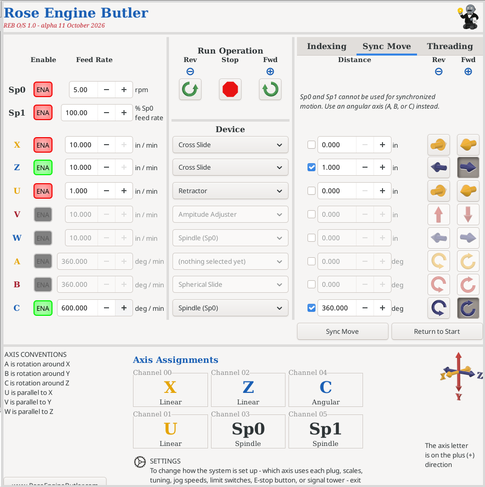
The Sync Move tab is used to drive synchronized movement of multiple motors.
Linear Axes
For linear axes, this is a distance. The UOM shown for these axes, and used by the system, is based on the Measurement System selection.
Angular Axes
For the angular axes, this is a rotary indexing. It can be in either:
- degrees
With LinuxCNC, synchronized motion of the spindles cannot be achieved using Sp0 nor Sp1. Those motors must be attached to an angular axis (A, B, or C). It is a good idea to perform a "dry run" to ensure everything moves as expected. You may need to change the setup for the axes (e.g., the Scale) to achieve your desired movements.
Using the Sync Move Tab
To drive movement on an axis,
- The axis must be ENAbled. In the picture to the right, X, Z, U, & V axes are enabled.
- The feed rate for the axis must be a non-zero number. Note: all the selected axes start and finish together. The move takes as long as whichever axis needs the most time at its own feed rate, so no axis moves faster than the feed rate you set for it.
- The axis must be selected. In the picture to the right, the blue tick boxes indicate that the X, Z, U, & V axes have been selected for use.
- The distance to move the axis must be a non-zero number.
- A direction of movement for the axis must be selected. In the picture to the right,
- X is to move in the reverse direction.
- Z is to move in the reverse direction.
- U is to move in the forward direction.
- V is to move in the reverse direction.
To initiate the movement, click on the Sync Move button below the axis distance fields. To return the system to where it was, click on the Return to Start button.
| spacer line |
|
eMail comments to |