
Cable Wire Color Scheme for the Spindle (Sp0) and Rosette Phaser Multiplier (Sp1)
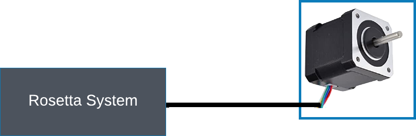
Cabling the spindle (Sp0) and the rosette phaser/multiplier (Sp1)
The Rose Engine Butler system cable wire color scheme is outlined in the table below.
This follows the overall scheme as outlined to the right.
Note:This scheme should only be used for the Spindle or the Rosette Phaser/Multiplier.
Cable Sizing
The cable between the Rose Engine Butler system and your device should be a 6-conductor cable. We recognize that limit switches are not used with spindles, but it is recommended that a 6-wire cable be used.
The connector cables we supply have GX/16-6 female connectors on both ends. At the device end of the cable, the stepper motor will be connected to the first 4 pins on the GX/16-6 male connector, leaving the other two unused.
Using this approach will keep the the connectors and connecting cables consistent and will not require you to keep multiple sizes and types of cables around.
The wires in the cable should be a minimum of 20 AWG (gauge). This will ensure the wire can easily handle the amperage for the NEMA 23 stepper motors.
|
GX-16 Pin |
Stepper Motor |
Limit Switch |
Comments | |
|
Stepper Online Wire Color |
Purpose | |||
|
1 |
Black |
A+ |
n/a |
|
|
2 |
Green |
A- |
| |
|
2 |
Red |
B+ |
| |
|
2 |
Blue |
B- |
| |
|
5 |
n/a |
n/a |
n/a |
Not Used |
|
6 | ||||
| spacer line |
|
eMail comments to |