
Cabling an E-Stop Button to Rose Engine Butler
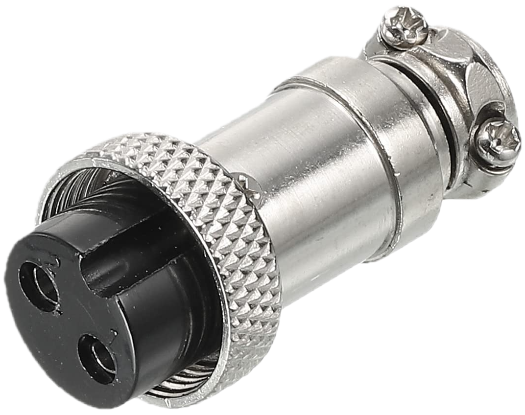
GX-16/2 Plug
Connector
A GX-16/2 female plug is used to connect this switch to the Rose Engine Butler system. This is sometimes called an aviation connector.
Cable Sizing
The cable between the Rose Engine Butler system and your E-stop button should:
- Have 2 conductors within the cable
- Be stranded - this is more flexible than solid wire
- Be 22 AWG (gauge; 24 AWG is the minimum) - this is easily soldered to the GX-16 connector
- Be shielded, with the shield connected to ground at the Rose Engine Butler box end only - this will help isolate the signal from noise which could be encountered in adjacent cables (e.g., for stepper motors)
Wiring the Switch
| GX-16 Pin | Wire Color | Purpose |
| 1 | Red | Signal (to the Rose Engine Butler input) - do not connect to any power source |
| 2 | Black | GND (ground) |
E-Stop Button Notes
E-stop switches are wired as normally closed, and the circuit becomes open when the switch is triggered.
The E-stop button simply connects the two pins together when it is not pressed. The Rose Engine Butler box supplies the signal itself, so never connect either wire to a power supply.
The E-stop button plugs into the Base Box.
The use of such a switch must be configured on the Inputs, Outputs, and Sounds tab of the Rose Engine Butler Settings program. See E-Stop for how the button works together with the F1 key.
|
eMail comments to |