
Inputs, Outputs, and Sounds
Key Note: The configuration program cannot be run when the Rose Engine Butler program is running. It is designed so that you configure the way Rose Engine Butler works, then run the system.
|
Limit Switches
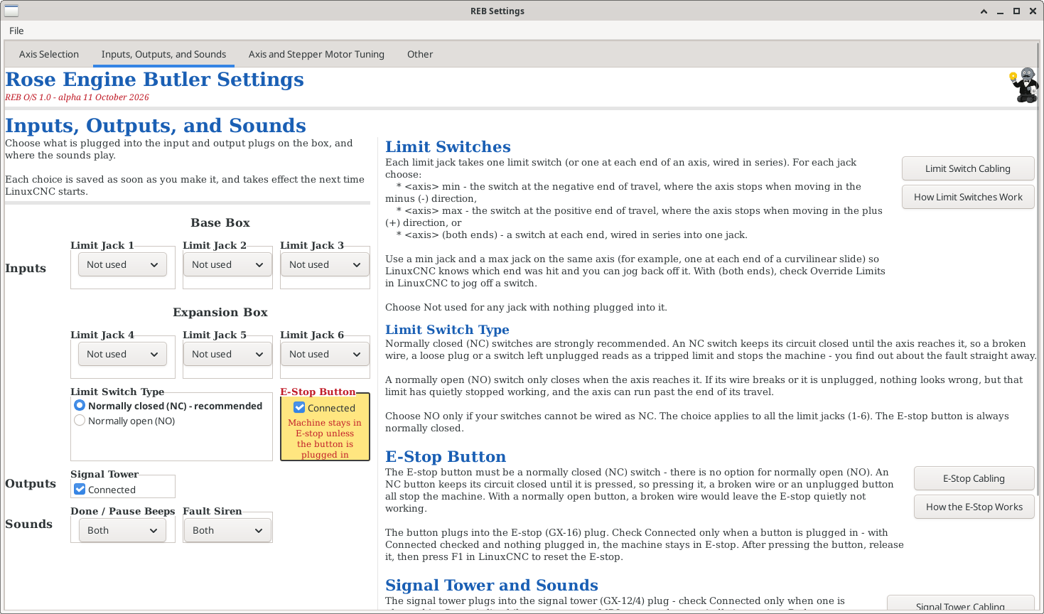
To use a limit switch, you need to assign it to an axis. The system is configured to accommodate 6 limit switches: Limit Jacks 1 - 3 on the Base Box, and Limit Jacks 4 - 6 on the optional Expansion Box. By default, they are not enabled.
Limit Jacks 4 - 6 can only be used when the Expansion Box is ticked as Connected on the Axis Selection tab. Otherwise they are greyed out; they keep their setting, ready for when the Expansion Box is connected.
The limit switches are defined to be normally closed (NC), so once they are enabled, the axes to which they are assigned will be in a limit mode until
- a switch is connected to the system, and
- that switch is not triggered.
Each Limit Jack only lists the axes which are assigned to a channel. Choose Not used for any jack with nothing plugged into it.
Limit switches can be configured 3 ways:
- For both ends (as shown for Limit Jack 1 to the right). This will enable the user to connect two or more switches in series, and if any of those breaks the circuit, the limit is triggered for that axis.
- For the min end (as shown for Limit Jack 2 to the right). This will trigger a limit when movement hits the minimum movement. By convention, this is in the negative side of movement. For example, on the Z axis, this would be on the left side.
- For the max end (as shown for Limit Jack 3 to the right). This will trigger a limit when movement hits the maximum movement. By convention, this is in the positive side of movement. For example, on the Z axis, this would be on the right side.
When a limit switch is tripped, LinuxCNC turns the machine off. With separate min and max jacks, LinuxCNC knows which end was hit, so after powering back on (F2) you can jog the axis away from the switch normally. With both ends, LinuxCNC can't tell which end was hit, so you need to check Override Limits (in LinuxCNC's Machine menu) to jog off the switch - take care to move away from it.
Two jacks can be used on the same axis only as a min and max pair; any other combination is flagged as Duplicate! or Conflict! and is not saved until it is corrected.
Notes:
- Spindles using the Sp0 or Sp1 connections cannot have limit switches assigned to them.
- Cabling for the limit switches.
E-Stop Button
For the E-Stop button, this is either set as connected, or not. The E-Stop button plugs into the Base Box.
The E-Stop button is defined as a normally closed (NC) circuit, so once the circuit encounters a break (i.e., when the E-Stop button is engaged), the system will move to an Emergency Stop status.
Key Note: As this is a normally closed circuit, once the use of an E-Stop button is enabled, the system cannot be taken out of Emergency Stop until
- a button is attached to the system and
- it is in a disengaged state.
Note:
- Cabling for the E-Stop button
- Usage instructions for the E-Stop button
Signal Tower
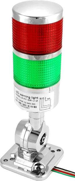
The signal tower plugs into the Base Box. It is setup in Rose Engine Butler to have 3 outputs:

| RED LIGHT: A signal which lights a red light when:
It does not light for:
|

| GREEN LIGHT: A signal which lights a green light to indicate that the system is running an operation:
It does not light for:
|

| BUZZER: A buzzer is set to sound for certain situations. Those are outlined below in sounds. |
Note:
- Cabling for the signal tower.
Sounds
There are two options for sounds:
- Operation Done - 3 beeps when an operation is completed. This is sounded only for those operations which also turn the green light on:
- Running one of the defined operations in the operator panel
- Running a Gcode command
- Running an MDI command
- While a running program is paused
- Pause - 2 beeps when an M0 or M1 Gcode (pause) is encountered.
- Fault - a 3 second sound. This is sounded only for those operations which also turn the red light on:
- A “following error” is encountered on any active axis. The red light stays lit until the machine is turned back on (F2).
- A limit switch is tripped on any in-use limit jack. The red light stays lit until the limit switch is no longer tripped.
- The Base Box or Expansion Box loses contact with the Raspberry Pi.
Either of the following can be configured to play a sound:
- Signal Tower’s siren,
- Monitor’s speaker (via HDMI), or
- Both
|
|
Running the Rose Engine Butler Settings Program
To access the Rose Engine Butler Settings program, there are 3 options:
|
|
Option 1: Use the icon on the desktop

Double-click on the Rose Engine Butler Settings icon on the desktop (the big gear)
|
|
Option 2: Use the Applications menu
- Click on Applications at the top left corner of the screen
- Click on the arrow to the right of Rose Engine Butler
- Click on Rose Engine Butler Settings (the one with a gear)
| Applications | |
 Rose Engine Butler > Rose Engine Butler >
| Rose Engine Butler
|
| Rose Engine Butler Settings
| |
 Backup Rose Engine Butler Backup Rose Engine Butler
| |
 Update Rose Engine Butler Update Rose Engine Butler
| |
|
|
Option 3: Run the command directly
Run this command from a terminal window:
|
bash /home/reuben/linuxcnc/configs/RoseEngineButler/REB_Settings.sh |
| spacer line |
|
eMail comments to |